|
Arduino Core for STM32
1.0
|
|
Arduino Core for STM32
1.0
|
Methods for change periphery settings. For every setting method, there is also method, that reads the current setting right from register. More...
Functions | |
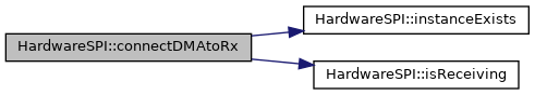
| bool | HardwareSPI::connectDMAtoRx (DMA_HandleTypeDef &DMA_handle) |
| Use this method to connect DMA channel to SPI Rx programmatically. More... | |
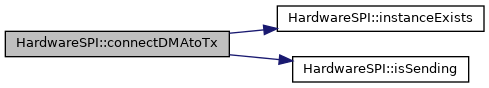
| bool | HardwareSPI::connectDMAtoTx (DMA_HandleTypeDef &DMA_handle) |
| Use this method to connect DMA channel to SPI Tx programmatically. More... | |
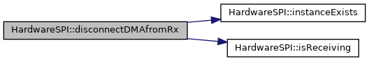
| bool | HardwareSPI::disconnectDMAfromRx () |
| Disconnects DMA channel from SPI Rx. More... | |
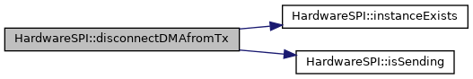
| bool | HardwareSPI::disconnectDMAfromTx () |
| Disconnects DMA channel from SPI Tx. More... | |
| bool | HardwareSPI::isDMAconnectedToRx (void) |
| Checks if DMA channel is connected to SPI Rx and can be used for data receiving/transferring. More... | |
| bool | HardwareSPI::isDMAconnectedToTx (void) |
| Checks if DMA channel is connected to SPI Tx and can be used for data writing/transferring. More... | |
| uint32_t | HardwareSPI::getSPIClockFreq (void) |
| Gets periphery SPI Clock Frequency in Hz. More... | |
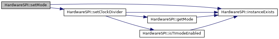
| bool | HardwareSPI::setMode (uint32_t mode) |
| Sets Master or Slave mode. More... | |
| uint32_t | HardwareSPI::getMode () |
| Gets, if periphery mode is Master or Slave. More... | |
| bool | HardwareSPI::setHwCS (bool HardwareCS, bool OutputCS=true) |
| Sets if Chip Select pin is handled by hardware or by software (calling digitalWrite()). More... | |
| bool | HardwareSPI::isHwCS () |
| Gets, if Chip Select is handled by hardware. More... | |
| bool | HardwareSPI::isHwOutputCS () |
| Gets, if Chip Select handled by hardware is set to output mode. More... | |
| bool | HardwareSPI::setBitOrder (uint8_t bitOrder) |
| Sets bit order to LSB or MSB. More... | |
| uint8_t | HardwareSPI::getBitOrder () |
| Gets, if bit order is set to LSB or MSB. More... | |
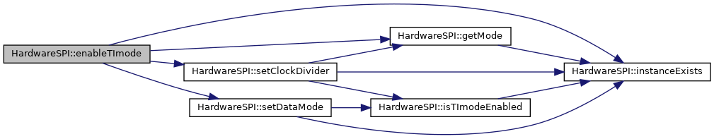
| bool | HardwareSPI::setDataMode (uint8_t dataMode) |
| Sets data mode. More... | |
| uint8_t | HardwareSPI::getDataMode () |
| Gets, what data mode is set. More... | |
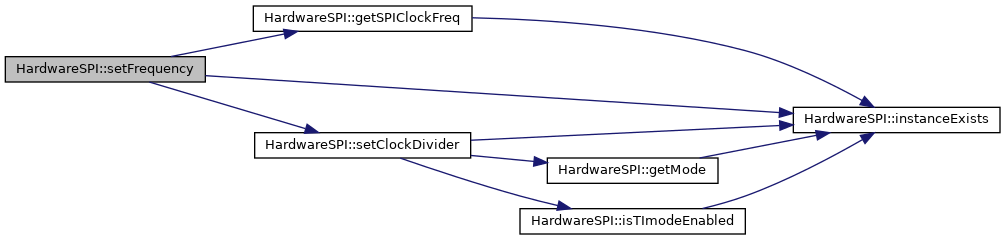
| bool | HardwareSPI::setFrequency (uint32_t freq) |
| Calculates SPI clock divider from frequency and sets it. More... | |
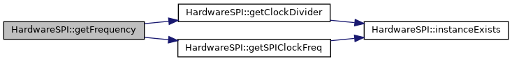
| uint32_t | HardwareSPI::getFrequency () |
| Calculates SPI frequency from APB frequency and Clock Divider. More... | |
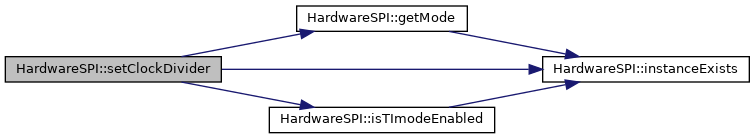
| bool | HardwareSPI::setClockDivider (uint32_t clockDiv) |
| Sets SPI clock divider. More... | |
| uint32_t | HardwareSPI::getClockDivider () |
| Gets clock divider. More... | |
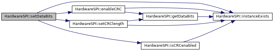
| bool | HardwareSPI::setDataBits (uint16_t bits) |
| Sets SPI data width in bits. More... | |
| uint16_t | HardwareSPI::getDataBits () |
| Gets set data width in bits. More... | |
| bool | HardwareSPI::enableTImode (bool enable) |
| Enables or disabled TI mode. More... | |
| bool | HardwareSPI::isTImodeEnabled () |
| Gets if TI mode is enabled. More... | |
| bool | HardwareSPI::enableCRC (bool enable) |
| Enables CRC. More... | |
| bool | HardwareSPI::isCRCenabled () |
| Gets if CRC is enabled. More... | |
| bool | HardwareSPI::setCRClength (SPI_CRCLength length) |
| Sets CRC length. More... | |
| SPI_CRCLength | HardwareSPI::getCRClength () |
| Gets CRC length. More... | |
| bool | HardwareSPI::setCRCPolynomial (uint32_t polynomial) |
| Sets CRC polynomial. More... | |
| uint32_t | HardwareSPI::getCRCPolynomial () |
| Gets CRC polynomial. More... | |
| void | HardwareSPI::setTimeout (uint32_t Timeout) |
| Sets timeout in milliseconds. More... | |
| uint32_t | HardwareSPI::getTimeout () |
| Gets timeout in milliseconds. More... | |
Methods for change periphery settings. For every setting method, there is also method, that reads the current setting right from register.
| bool HardwareSPI::connectDMAtoRx | ( | DMA_HandleTypeDef & | DMA_handle | ) |
Use this method to connect DMA channel to SPI Rx programmatically.
| DMA_handle | DMA channel handle structure, you want to connect. |
| bool HardwareSPI::connectDMAtoTx | ( | DMA_HandleTypeDef & | DMA_handle | ) |
Use this method to connect DMA channel to SPI Tx programmatically.
| DMA_handle | DMA channel handle structure, you want to connect. |
| bool HardwareSPI::disconnectDMAfromRx | ( | ) |
Disconnects DMA channel from SPI Rx.
| bool HardwareSPI::disconnectDMAfromTx | ( | ) |
Disconnects DMA channel from SPI Tx.
| bool HardwareSPI::isDMAconnectedToRx | ( | void | ) |
Checks if DMA channel is connected to SPI Rx and can be used for data receiving/transferring.
| bool HardwareSPI::isDMAconnectedToTx | ( | void | ) |
Checks if DMA channel is connected to SPI Tx and can be used for data writing/transferring.
| uint32_t HardwareSPI::getSPIClockFreq | ( | void | ) |
Gets periphery SPI Clock Frequency in Hz.

| bool HardwareSPI::setMode | ( | uint32_t | mode | ) |
Sets Master or Slave mode.
| mode | Master or Slave mode. (Use macros: SPI_MASTER and SPI_SLAVE) |
| uint32_t HardwareSPI::getMode | ( | ) |
Gets, if periphery mode is Master or Slave.

| bool HardwareSPI::setHwCS | ( | bool | HardwareCS, |
| bool | OutputCS = true |
||
| ) |
Sets if Chip Select pin is handled by hardware or by software (calling digitalWrite()).
| HardwareCS | True to use hardware Chip Select. |
| OutputCS | True to use hardware Chip Select in output mode (Default value: true). This parameter is ignored when HardwareCS is set to false. |

| bool HardwareSPI::isHwCS | ( | ) |
Gets, if Chip Select is handled by hardware.

| bool HardwareSPI::isHwOutputCS | ( | ) |
Gets, if Chip Select handled by hardware is set to output mode.

| bool HardwareSPI::setBitOrder | ( | uint8_t | bitOrder | ) |
Sets bit order to LSB or MSB.
| bitOrder | Use macros: LSBFIRST or MSBFIRST. |

| uint8_t HardwareSPI::getBitOrder | ( | ) |
Gets, if bit order is set to LSB or MSB.

| bool HardwareSPI::setDataMode | ( | uint8_t | dataMode | ) |
Sets data mode.
| dataMode | Selected data mode. Use values from the table below:
|
SPI_MODE0 0x00 - CPOL: 0 CPHA: 0 SPI_MODE1 0x01 - CPOL: 0 CPHA: 1 SPI_MODE2 0x10 - CPOL: 1 CPHA: 0 SPI_MODE3 0x11 - CPOL: 1 CPHA: 1
< CPOL (Clock Polarity)
< CPHA (Clock Phase)

| uint8_t HardwareSPI::getDataMode | ( | ) |
Gets, what data mode is set.
| SPI mode | CPOL | CPHA |
|---|---|---|
| SPI_MODE0 | 0 | 0 |
| SPI_MODE1 | 0 | 1 |
| SPI_MODE2 | 1 | 0 |
| SPI_MODE3 | 1 | 1 |
SPI_MODE0 0x00 - CPOL: 0 CPHA: 0 SPI_MODE1 0x01 - CPOL: 0 CPHA: 1 SPI_MODE2 0x10 - CPOL: 1 CPHA: 0 SPI_MODE3 0x11 - CPOL: 1 CPHA: 1
< CPOL (Clock Polarity)
< CPHA (Clock Phase)

| bool HardwareSPI::setFrequency | ( | uint32_t | freq | ) |
Calculates SPI clock divider from frequency and sets it.
| freq | Frequency in Hz. |
| uint32_t HardwareSPI::getFrequency | ( | ) |
Calculates SPI frequency from APB frequency and Clock Divider.
| bool HardwareSPI::setClockDivider | ( | uint32_t | clockDiv | ) |
Sets SPI clock divider.
The real frequency depends on the APB clock frequency and clock divider.
| clockDiv | Clock divider value. Use one of the defined value from SPI_Clock_Div. |
| uint32_t HardwareSPI::getClockDivider | ( | ) |
Gets clock divider.

| bool HardwareSPI::setDataBits | ( | uint16_t | bits | ) |
Sets SPI data width in bits.
| bits | Width of data in bits. Use values: 4 <= bits <= 16 |
| uint16_t HardwareSPI::getDataBits | ( | ) |
Gets set data width in bits.

| bool HardwareSPI::enableTImode | ( | bool | enable | ) |
Enables or disabled TI mode.
| enable | True to enable TI mode, false to enable Motorola mode. Motorola mode is used more often. |
| bool HardwareSPI::isTImodeEnabled | ( | ) |
Gets if TI mode is enabled.

| bool HardwareSPI::enableCRC | ( | bool | enable | ) |
Enables CRC.
| enable | True to enable CRC. |

| bool HardwareSPI::isCRCenabled | ( | ) |
Gets if CRC is enabled.

| bool HardwareSPI::setCRClength | ( | SPI_CRCLength | length | ) |
Sets CRC length.
| length | CRC length to be set. See SPI_CRCLength enum. |

| SPI_CRCLength HardwareSPI::getCRClength | ( | ) |
Gets CRC length.

| bool HardwareSPI::setCRCPolynomial | ( | uint32_t | polynomial | ) |
Sets CRC polynomial.
| polynomial | CRC polynomial. It is recommended to use macros: CRC_X0, CRC_X1, ..., CRC_X7; see: CRC_Poly_Terms. Polynomial have to contain CRC_X0. Polynomial doesn't have to contain highest coefficient, because it is added automatically from CRC length. For example CRC-8 polynomial is X^8 + X^5 + X^4 + 1, so you have to enter (CRC_X5 | CRC_X4 | CRC_X0), CRC_X8 is added automatically by CRC length. It's value have to be less than 256 and always has to be odd. |

| uint32_t HardwareSPI::getCRCPolynomial | ( | ) |
Gets CRC polynomial.

| void HardwareSPI::setTimeout | ( | uint32_t | Timeout | ) |
Sets timeout in milliseconds.
Timeout is used in all methods, that transact any data and in method HardwareSPI_O::endTransaction()
| Timeout | Timeout in milliseconds. |
| uint32_t HardwareSPI::getTimeout | ( | ) |
Gets timeout in milliseconds.
 1.8.17