|
Arduino Core for STM32
1.0
|
|
Arduino Core for STM32
1.0
|
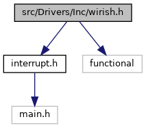
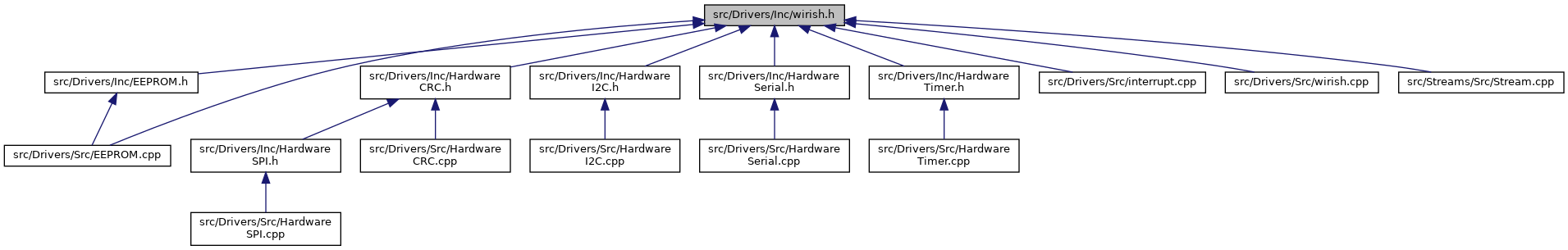
This file contains basic (Arduino like) GPIO manipulation functions, delay, random, etc. More...
Go to the source code of this file.
Macros | |
| #define | W_INT_HANDLING_MODE 2 |
| Interrupt GPIO handling mode. More... | |
| #define | W_OK 1 |
| Wirish status OK. More... | |
| #define | W_BAD_ARG -1 |
| Wirish status Bad Arguments. More... | |
| #define | W_ERR 0 |
| Wirish status Error. More... | |
| #define | PIN_TO_PORT_PIN(Pin) (0x01 << ((Pin)&0x0F)) |
| Converts Arduino like pin number (Pin) to Pin of port (PPin). More... | |
| #define | PIN_TO_PORT(Pin) (GPIO_Conversion_Table[(Pin)>>4]) |
| Converts Arduino like pin number (Pin) to GPIO port. More... | |
| #define | MIN(a, b) (((a)<(b))?(a):(b)) |
| Compares 2 values and returns lower one. More... | |
| #define | MAX(a, b) (((a)>(b))?(a):(b)) |
| Compares 2 values and returns higher one. More... | |
| #define | Abs(a) (((a)>=0)?(a):-(a)) |
| Absolute value of number. More... | |
| #define | lowByte(w) ((w) & 0xFF) |
| Extracts the low-order (rightmost) byte of a variable (e.g. More... | |
| #define | highByte(w) (((w) >> 8) & 0xFF) |
| Extracts the high-order (leftmost) byte of a word (or the second lowest byte of a larger data type). More... | |
| #define | bitRead(value, bit) (((value) >> (bit)) & 0x01) |
| Reads a bit of a number. More... | |
| #define | bitSet(value, bit) ((value) |= (1UL << (bit))) |
| Sets (writes a 1 to) a bit of a numeric variable. More... | |
| #define | bitClear(value, bit) ((value) &= ~(1UL << (bit))) |
| Clears (writes a 0 to) a bit of a numeric variable. More... | |
| #define | bitWrite(value, bit, bitvalue) |
| Writes a bit of a numeric variable. More... | |
| #define | bit(b) (1UL << (b)) |
| Computes the value of the specified bit (bit 0 is 1, bit 1 is 2, bit 2 is 4, etc.). More... | |
| #define | millis() HAL_GetTick() |
| Returns the number of milliseconds passed since the STM board began running the current program. More... | |
| #define | delay(millis) HAL_Delay(millis) |
| Pauses the program for the amount of time (in milliseconds) specified as parameter. More... | |
| #define | WAIT_US_CALIBRATION (18) |
| #define | cli() __disable_irq() |
| #define | noInterrupts() cli() |
| Disables interrupts (you can re-enable them with interrupts()). More... | |
| #define | sei() __enable_irq() |
| #define | interrupts() sei() |
| Re-enables interrupts (after they’ve been disabled by noInterrupts(). More... | |
| #define | HIGH 0x1 |
| HIGH pin state, same as 1. More... | |
| #define | LOW 0x0 |
| LOW pin state, same as 0. More... | |
| #define | LSBFIRST 0 |
| Least Significant Bit First. More... | |
| #define | MSBFIRST 1 |
| Most Significant Bit First. More... | |
| #define | CHANGE 1 |
| GPIO interrupt will be triggered when pin state change. More... | |
| #define | FALLING 2 |
| GPIO interrupt will be triggered when pin state change from HIGH to LOW. More... | |
| #define | RISING 3 |
| GPIO interrupt will be triggered when pin state change from LOW to HIGH. More... | |
| #define | RESET_CAUSE_POWER_ON_POWER_DOWN_RESET RESET_CAUSE_EXTERNAL_RESET_PIN_RESET |
| Power-ON reset, Power-DOWN reset cause. More... | |
Typedefs | |
| typedef enum WiringPinMode | WiringPinMode |
| typedef enum reset_cause_e | ResetCause |
| Possible STM32 system reset causes. More... | |
Enumerations | |
| enum | WiringPinMode { OUTPUT, OUTPUT_OPEN_DRAIN, INPUT, INPUT_ANALOG, INPUT_PULLUP, INPUT_PULLDOWN, INPUT_FLOATING } |
| Pin mode enumerations. More... | |
| enum | reset_cause_e { RESET_CAUSE_UNKNOWN = 0, RESET_CAUSE_LOW_POWER_RESET = 1, RESET_CAUSE_WINDOW_WATCHDOG_RESET = 2, RESET_CAUSE_INDEPENDENT_WATCHDOG_RESET = 3, RESET_CAUSE_SOFTWARE_RESET = 4, RESET_CAUSE_EXTERNAL_RESET_PIN_RESET = 6, RESET_CAUSE_BROWNOUT_RESET = 7 } |
| Possible STM32 system reset causes. More... | |
Functions | |
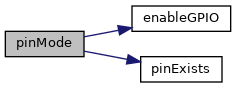
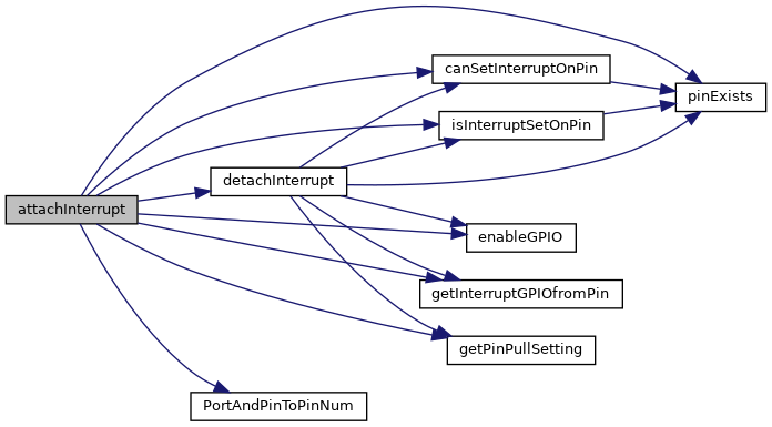
| bool | pinExists (GPIO_TypeDef *GPIOx, uint16_t PPin) |
| Checks if pin is available on MCU. More... | |
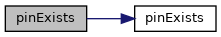
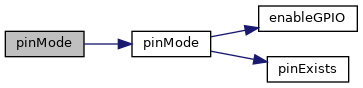
| bool | pinExists (uint8_t Pin) |
| Checks if pin is available on MCU. More... | |
| bool | enableGPIO (GPIO_TypeDef *GPIOx, bool enable) |
| Enables/Disables GPIO port periphery. More... | |
| uint8_t | PortAndPinToPinNum (GPIO_TypeDef *GPIOx, uint16_t PPin) |
| Converts GPIOx port and it's pin to Arduino like pin number. More... | |
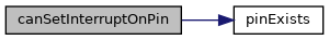
| bool | canSetInterruptOnPin (uint8_t Pin) |
| Checks if EXTI line, that belongs to Pin is not used by other pin's interrupt. More... | |
| GPIO_TypeDef * | getInterruptGPIOfromPin (uint16_t Pin) |
| Gets, what GPIO is attached to EXTI line, that belongs to PPin. More... | |
| bool | isInterruptSetOnPin (uint8_t Pin) |
| Checks Pin is used as interrupt. More... | |
| uint8_t | pinMode (GPIO_TypeDef *GPIOx, uint16_t PPin, WiringPinMode mode, uint32_t speed) |
| Sets mode of selected pin. More... | |
| void | digitalWrite (GPIO_TypeDef *GPIOx, uint16_t PPin, bool val) |
| Writes new state to pin or multiple pins. More... | |
| uint16_t | digitalRead (GPIO_TypeDef *GPIOx, uint16_t PPin) |
| Reads state of pin or multiple pins. More... | |
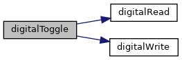
| void | digitalToggle (GPIO_TypeDef *GPIOx, uint16_t PPin) |
| Toggles pin state. More... | |
| uint8_t | pinMode (uint8_t Pin, WiringPinMode mode, uint32_t speed) |
| Sets mode of selected pin. More... | |
| uint8_t | pinMode (uint8_t Pin, WiringPinMode mode) |
| Sets mode of selected pin. More... | |
| void | digitalWrite (uint8_t Pin, bool val) |
| Writes new state to pin. More... | |
| bool | digitalRead (uint8_t Pin) |
| Reads state of pin. More... | |
| void | digitalToggle (uint8_t Pin) |
| Toggles state of pin. More... | |
| int8_t | attachInterrupt (uint8_t Pin, std::function< void(void)>, int mode) |
| Attaches interrupt to selected pin. More... | |
| int8_t | detachInterrupt (uint8_t Pin, bool disableEXTIwhenNotUsed=false) |
| Detaches interrupt from selected pin and sets pin mode to INPUT. More... | |
| void | InterruptHandler (uint8_t lineFrom, uint8_t lineTo) |
| Include this in every EXTI interrupt handler for lines 0-15. More... | |
| int8_t | isPinUsedByInt (uint8_t INTPPin) |
| Checks if pin is not used for interrupt. More... | |
| uint32_t | getPinPullSetting (GPIO_TypeDef *GPIOx, uint8_t INTPin) |
| This function should return actual pin pull setting (GPIO_NOPULL, GPIO_PULLUP, GPIO_PULLDOWN) More... | |
| uint32_t | getPinSpeedSetting (GPIO_TypeDef *GPIOx, uint8_t INTPin) |
| This should return actual pin toggle speed setting. More... | |
| bool | WirishInit (void) |
| Initializes some wirish functions. More... | |
| void | __attribute__ ((optimize("Ofast"))) delayMicrosecondsDWT(uint32_t microseconds) |
| Pauses the program for the amount of time (in microseconds) specified as parameter. More... | |
| unsigned long | random (unsigned long from, unsigned long to) |
| The random function generates pseudo-random numbers. More... | |
| unsigned long | random (unsigned long to) |
| The random function generates pseudo-random numbers. More... | |
| void | randomSeed (unsigned long seed) |
| Initializes the pseudo-random number generator, causing it to start at an arbitrary point in its random sequence. More... | |
| const char * | getResetCauseName () |
| Gets the system reset cause as an ASCII-printable name string from a reset cause type. More... | |
| ResetCause | getResetCause () |
| Reads the STM32 system reset cause. More... | |
| void | getDeviceLOTID (char *buffer) |
| Returns device LOT ID as text. More... | |
| uint8_t | getDeviceWAFID () |
| Gets device wafer plate ID. More... | |
| uint16_t | getDeviceWAFX () |
| Returns device wafer plate X coordination. More... | |
| uint16_t | getDeviceWAFY () |
| Gets device wafer plate Y coordination. More... | |
| uint32_t | getFlashSize () |
| Gets flash size in bytes. More... | |
Variables | |
| GPIO_TypeDef * | GPIO_Conversion_Table [] |
| ResetCause | rst_cs |
This file contains basic (Arduino like) GPIO manipulation functions, delay, random, etc.
| #define W_INT_HANDLING_MODE 2 |
Interrupt GPIO handling mode.
| #define W_OK 1 |
Wirish status OK.
| #define W_BAD_ARG -1 |
Wirish status Bad Arguments.
| #define W_ERR 0 |
Wirish status Error.
| #define PIN_TO_PORT_PIN | ( | Pin | ) | (0x01 << ((Pin)&0x0F)) |
Converts Arduino like pin number (Pin) to Pin of port (PPin).
| Pin | Arduino like pin number. |
| #define PIN_TO_PORT | ( | Pin | ) | (GPIO_Conversion_Table[(Pin)>>4]) |
Converts Arduino like pin number (Pin) to GPIO port.
| Pin | Arduino like pin number. |
| #define MIN | ( | a, | |
| b | |||
| ) | (((a)<(b))?(a):(b)) |
Compares 2 values and returns lower one.
| a | First value |
| b | Second value |
| #define MAX | ( | a, | |
| b | |||
| ) | (((a)>(b))?(a):(b)) |
Compares 2 values and returns higher one.
| a | First value |
| b | Second value |
| #define Abs | ( | a | ) | (((a)>=0)?(a):-(a)) |
Absolute value of number.
| a | value |
| #define lowByte | ( | w | ) | ((w) & 0xFF) |
Extracts the low-order (rightmost) byte of a variable (e.g.
a word).
| w | A value of any type. |
| #define highByte | ( | w | ) | (((w) >> 8) & 0xFF) |
Extracts the high-order (leftmost) byte of a word (or the second lowest byte of a larger data type).
| w | A value of any type. |
Reads a bit of a number.
| value | The number from which to read. |
| bit | Which bit to read, starting at 0 for the least-significant (rightmost) bit. |
Sets (writes a 1 to) a bit of a numeric variable.
| value | The numeric variable whose bit to set. |
| bit | Which bit to set, starting at 0 for the least-significant (rightmost) bit. |
Clears (writes a 0 to) a bit of a numeric variable.
| value | The numeric variable whose bit to set. |
| bit | Which bit to clear, starting at 0 for the least-significant (rightmost) bit. |
| #define bitWrite | ( | value, | |
| bit, | |||
| bitvalue | |||
| ) |
Writes a bit of a numeric variable.
| value | The numeric variable to which to write. |
| bit | Which bit of the number to write, starting at 0 for the least-significant (rightmost) bit. |
| bitvalue | The value to write to the bit (0 or 1). |
| #define bit | ( | b | ) | (1UL << (b)) |
Computes the value of the specified bit (bit 0 is 1, bit 1 is 2, bit 2 is 4, etc.).
| b | The bit whose value to compute |
| #define millis | ( | ) | HAL_GetTick() |
Returns the number of milliseconds passed since the STM board began running the current program.
This number will overflow (go back to zero), after approximately 50 days.
Pauses the program for the amount of time (in milliseconds) specified as parameter.
(There are 1000 milliseconds in a second.)
| millis | The number of milliseconds to pause. |
| #define WAIT_US_CALIBRATION (18) |
| #define cli | ( | ) | __disable_irq() |
| #define noInterrupts | ( | ) | cli() |
Disables interrupts (you can re-enable them with interrupts()).
Interrupts allow certain important tasks to happen in the background and are enabled by default. Some functions will not work while interrupts are disabled, and incoming communication may be ignored. Interrupts can slightly disrupt the timing of code, however, and may be disabled for particularly critical sections of code.
| #define sei | ( | ) | __enable_irq() |
| #define interrupts | ( | ) | sei() |
Re-enables interrupts (after they’ve been disabled by noInterrupts().
Interrupts allow certain important tasks to happen in the background and are enabled by default. Some functions will not work while interrupts are disabled, and incoming communication may be ignored. Interrupts can slightly disrupt the timing of code, however, and may be disabled for particularly critical sections of code.
| #define HIGH 0x1 |
HIGH pin state, same as 1.
| #define LOW 0x0 |
LOW pin state, same as 0.
| #define LSBFIRST 0 |
Least Significant Bit First.
| #define MSBFIRST 1 |
Most Significant Bit First.
| #define CHANGE 1 |
| #define FALLING 2 |
GPIO interrupt will be triggered when pin state change from HIGH to LOW.
| #define RISING 3 |
GPIO interrupt will be triggered when pin state change from LOW to HIGH.
| #define RESET_CAUSE_POWER_ON_POWER_DOWN_RESET RESET_CAUSE_EXTERNAL_RESET_PIN_RESET |
Power-ON reset, Power-DOWN reset cause.
| typedef enum WiringPinMode WiringPinMode |
| typedef enum reset_cause_e ResetCause |
Possible STM32 system reset causes.
| enum WiringPinMode |
Pin mode enumerations.
| enum reset_cause_e |
Possible STM32 system reset causes.
| bool pinExists | ( | GPIO_TypeDef * | GPIOx, |
| uint16_t | PPin | ||
| ) |
Checks if pin is available on MCU.
| GPIOx | GPIO port periphery. |
| PPin | Pin of that port to convert (GPIO_PIN_0, GPIO_PIN_1, ...). Do not use combined pins (e.g. GPIO_PIN_0 | GPIO_PIN_1) |
| bool pinExists | ( | uint8_t | Pin | ) |
Checks if pin is available on MCU.
| Pin | Arduino like pin number. |
| bool enableGPIO | ( | GPIO_TypeDef * | GPIOx, |
| bool | enable | ||
| ) |
Enables/Disables GPIO port periphery.
| GPIOx | GPIO port periphery. |
| enable | If true, periphery will be enabled, else disabled. |
| uint8_t PortAndPinToPinNum | ( | GPIO_TypeDef * | GPIOx, |
| uint16_t | PPin | ||
| ) |
Converts GPIOx port and it's pin to Arduino like pin number.
| GPIOx | GPIO port. |
| PPin | Pin of that port to convert (GPIO_PIN_0, GPIO_PIN_1, ...). Do not use combined pins (e.g. GPIO_PIN_0 | GPIO_PIN_1) |
| bool canSetInterruptOnPin | ( | uint8_t | Pin | ) |
Checks if EXTI line, that belongs to Pin is not used by other pin's interrupt.
| Pin | Arduino like pin number. |
| GPIO_TypeDef* getInterruptGPIOfromPin | ( | uint16_t | Pin | ) |
Gets, what GPIO is attached to EXTI line, that belongs to PPin.
| Pin | Arduino like pin number. |
| bool isInterruptSetOnPin | ( | uint8_t | Pin | ) |
Checks Pin is used as interrupt.
| Pin | Arduino like pin number. |

| uint8_t pinMode | ( | GPIO_TypeDef * | GPIOx, |
| uint16_t | PPin, | ||
| WiringPinMode | mode, | ||
| uint32_t | speed | ||
| ) |
Sets mode of selected pin.
| GPIOx | GPIO port. |
| PPin | Pin of that port (GPIO_PIN_0, GPIO_PIN_1, ...). |
| mode | Pin mode that will be set. |
| speed | Toggle speed of pin. Available values: GPIO_SPEED_FREQ_LOW, GPIO_SPEED_FREQ_MEDIUM, GPIO_SPEED_FREQ_HIGH, GPIO_SPEED_FREQ_VERY_HIGH (only some MCUs supports this speed setting)) |
|
inline |
Writes new state to pin or multiple pins.
| GPIOx | GPIO port. |
| PPin | Pin of that port (GPIO_PIN_0, GPIO_PIN_1, ...). |
| val | Boolean state that will be written to the pin or multiple pins on same GPIO port. |
|
inline |
Reads state of pin or multiple pins.
| GPIOx | GPIO port. |
| PPin | Pin of that port (GPIO_PIN_0, GPIO_PIN_1, ...). |
|
inline |
Toggles pin state.
| GPIOx | GPIO port. |
| PPin | Pin of that port (GPIO_PIN_0, GPIO_PIN_1, ...). |
| uint8_t pinMode | ( | uint8_t | Pin, |
| WiringPinMode | mode, | ||
| uint32_t | speed | ||
| ) |
Sets mode of selected pin.
| Pin | Arduino like pin number. |
| mode | Pin mode that will be set. |
| speed | Toggle speed of pin. Available values: GPIO_SPEED_FREQ_LOW, GPIO_SPEED_FREQ_MEDIUM, GPIO_SPEED_FREQ_HIGH, GPIO_SPEED_FREQ_VERY_HIGH (only some MCUs supports this speed setting)) |

|
inline |
Sets mode of selected pin.
| Pin | Arduino like pin number. |
| mode | Pin mode that will be set. |
|
inline |
Writes new state to pin.
| Pin | Arduino like pin number. |
| val | Boolean state that will be written to the pin. |
|
inline |
Reads state of pin.
| Pin | Arduino like pin number. |
|
inline |
Toggles state of pin.
| Pin | Arduino like pin number. |
| int8_t attachInterrupt | ( | uint8_t | Pin, |
| std::function< void(void)> | , | ||
| int | mode | ||
| ) |
Attaches interrupt to selected pin.
| Pin | Arduino like pin. |
| handler | Function, that will be called when interrupt is triggered. |
| mode | Mode of interrupt (RISING, FALLING, CHANGE). |
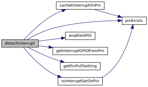
| int8_t detachInterrupt | ( | uint8_t | Pin, |
| bool | disableEXTIwhenNotUsed = false |
||
| ) |
Detaches interrupt from selected pin and sets pin mode to INPUT.
| Pin | Arduino like pin number. |
| disableEXTIwhenNotUsed | True if you want to disable group of EXTI lines when they are not used yet. It can save energy, but it can also disable GPIO interrupt, that is set using .ioc file. |
| void InterruptHandler | ( | uint8_t | lineFrom, |
| uint8_t | lineTo | ||
| ) |
Include this in every EXTI interrupt handler for lines 0-15.
| lineFrom | Specify first handler line |
| lineTo | Specify last handler line |
| int8_t isPinUsedByInt | ( | uint8_t | INTPPin | ) |
Checks if pin is not used for interrupt.
It also check if pin with same number on different port is not used for interrupt. (e.g. when port PA01 is interrupt, ports PB01, PC01, PD01,... cannot be used as interrupt.
| INTPPin | Arduino like pin number or INTPin number (0-15). |
| uint32_t getPinPullSetting | ( | GPIO_TypeDef * | GPIOx, |
| uint8_t | INTPin | ||
| ) |
This function should return actual pin pull setting (GPIO_NOPULL, GPIO_PULLUP, GPIO_PULLDOWN)
| GPIOx | GPIO port. |
| INTPin | Interrupt pin number (0-15). |
| uint32_t getPinSpeedSetting | ( | GPIO_TypeDef * | GPIOx, |
| uint8_t | INTPin | ||
| ) |
This should return actual pin toggle speed setting.
| GPIOx | GPIO port. |
| INTPin | Interrupt pin number (0-15). |
| bool WirishInit | ( | void | ) |
Initializes some wirish functions.
|
inline |
Pauses the program for the amount of time (in microseconds) specified as parameter.
Returns the number of microseconds since the MCU began running the current program.
(There are 1 million microseconds in a second.) Main advantage of this function is, that any interrupt does not stop delay counter. Main disadvantage is that it's resolution is not as good as delayMicroseconds resolution and also calculation takes more time.
| microseconds | The number of microseconds to pause. |
(There are 1 million microseconds in a second.) Main advantage of this function is, that it have really good resolution (only 3 ticks) and fast calculation time (around 23 ticks). Main disadvantage is that interrupt can extend delay time, when code is interrupted during delay.
| microseconds | The number of microseconds to pause. |
| unsigned long random | ( | unsigned long | from, |
| unsigned long | to | ||
| ) |
The random function generates pseudo-random numbers.
| from | Lower bound of the random value, inclusive (optional). |
| to | Upper bound of the random value, exclusive. |
| unsigned long random | ( | unsigned long | to | ) |
The random function generates pseudo-random numbers.
| to | Upper bound of the random value, exclusive. |

| void randomSeed | ( | unsigned long | seed | ) |
Initializes the pseudo-random number generator, causing it to start at an arbitrary point in its random sequence.
This sequence, while very long, and random, is always the same.
| seed | Number to initialize the pseudo-random sequence. |
| const char* getResetCauseName | ( | ) |
Gets the system reset cause as an ASCII-printable name string from a reset cause type.
| reset_cause | The previously-obtained system reset cause |
|
inline |
Reads the STM32 system reset cause.
|
inline |
Returns device LOT ID as text.
| Pointer | to buffer, where LOT ID will be copied. Buffer has to be 8 bytes long. |
|
inline |
Gets device wafer plate ID.
|
inline |
Returns device wafer plate X coordination.
|
inline |
Gets device wafer plate Y coordination.
|
inline |
Gets flash size in bytes.
| GPIO_TypeDef* GPIO_Conversion_Table[] |
| ResetCause rst_cs |
 1.8.17