


Gait Analyser
Firmware for STM32 - Gait Analyser. Support serveral ICM20948 sensors. Communicate wirh IMU sensors and send measured data to serial port.
Basic properties:
- support up to 2 IMU sensors
- read acceleration and angle velocity (gyroscope)
- communication interface: USB (virtual com port)
Communication parameters:
- cummunication interface: UART
- speed: 921600 Baud
Operational modes:
- MANAGE - to set/get sesor or module parameters. The measuremet is not active in this mode.
- RUN - Module is measuring and sending data.
Used modules:
- ICM20948 - driver for sensors
- DataFrame - create data packets
- API - communication protocol
Hardware connection
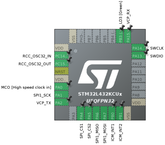
SPI1:
- MISO - PA6 (A5)
- MOSI - PA7 (A6)
- SCK - PA1 (A1)
- IMU sensors:
- CS1 - PA4 (A3)
- CS2 - PA5 (A4)
- CS3 - N/A
- INT1 - PB0 (D3)
- INT2 - PB1 (D6)
- INT3 - N/A
- Radio Transmitter
- CS - N/A
LED - PB3 (D13)
UART
- RX - PA15 - not wired to pin header
- TX - PA2 (A7)
Communication protocol - MANAGE mode
It is used binary communication protocol with special properites:
- no byte can have value 0x0
- only the last (terminating) byte is 0x0
Packet structure:
Request:
| Byte | 0 | 1 | 2..(n-3) | n-2 | n-1 |
|---|---|---|---|---|---|
| Meaning | Address | Function | Data | CRC | TERM |
- Address: index of sensor. Allowed values:
- for sensors: 1,2,3... up to real number od attached sensors (SENSOR_INDEX)
- for MCU: MODULE_ADDR (0x70)
- Function: Requred functionality
- this code is calculated as binary sum of: CMD_DIRECTION and CMD_CODE
- Data: optional part.
- CRC: CRC8 algorithm with CRC polymome (POLY=0x97) : x^8 + x^7 + x^4 + x^2 + x^1 +1
- TERM: termination character - 0x0
CMD_DIRECTION:
- SET: 0x00
- GET: 0x80
Response OK:
| Byte | 0 | 1 | 2..(n-3) | n-2 | n-1 |
|---|---|---|---|---|---|
| Meaning | Address | Function* | Data | CRC | TERM |
- Function* - Function code without READ prefix
Response ERR:
| Byte | 0 | 1 | 2..(n-3) | n-2 | n-1 |
|---|---|---|---|---|---|
| Meaning | Address* | Function* | Error Code | CRC | TERM |
- Function* - Function code without READ prefix
- Address* - Adress | 0x80
Error Code:
- 0x10 - Not supported
- 0x11 - Bad parameters
- 0x12 - Not ready
- 0x13 - Sensor not exists
Supported functionality
1-st byte is fuction code. The code is coposec from these parts:
- Read/Write flag
- READ: 0x80
- WRITE: 0x00
- Functionality - see table bellow
- Target for command exucution - DESTINATION
- DEST_MODULE 0x00 (IMU Sensor/all sensors)
- DEST_ACC: 0x01 (Accelerometer)
- DEST_GYRO: 0x02 (Gyroscope)
- DEST_MAG: 0x03 (Magnetometer)
Supported fuction codes
| Function name | Code | Description |
|---|---|---|
| CMD_ECHO | 0x04 | Echo response |
| CMD_STOP | 0x08 | Stop reading data |
| CMD_START | 0x0C | Start readig data |
| CMD_SAMPLERATE | 0x10 | Modify samplerate |
| CMD_LOWPASSFIL | 0x14 | Modify cut-off frequency for LPF |
| CMD_RANGE | 0x18 | Modify sensor range |
| CMD_SENSOR_CNT | 0x1C | Get total number of sensor cout |
| CMD_SLEEP | 0x20 | Go to sleep mode |
| CMD_WAKEUP | 0x24 | Wakeup from sleep |
| CMD_CALIBRATE | 0x28 | Run calibration procedure on sensor or its part |
| CMD_RESET | 0x2C | Reset the IMU and apply factory settings |
| CMD_STORE | 0x30 | Store/Read IMU settings to/from internal memory |
| CMD_DATA | 0x34 | Read raw data from sensor |
Supported function code generation for selected sensor
| Function | MCU part of address |
SENSOR | ACC | GYRO | MAG |
|---|---|---|---|---|---|
| CMD_ECHO | GET/- | -/- | -/- | -/- | -/- |
| CMD_STOP | -/SET | GET/SET | -/- | -/- | -/- |
| CMD_START | -/SET | GET/SET | -/- | -/- | -/- |
| CMD_SAMPLERATE | -/- | -/- | GET/SET | GET/SET | GET/SET |
| CMD_LOWPASSFIL | -/- | -/- | GET/SET | GET/SET | GET/SET |
| CMD_RANGE | -/- | -/- | GET/SET | GET/SET | GET/SET |
| CMD_SENSOR_CNT | GET/- | -/- | -/- | -/- | -/- |
| CMD_SLEEP | -/- | GET/SET | -/- | -/- | -/- |
| CMD_WAKEUP | -/- | GET/SET | -/- | -/- | -/- |
| CMD_CALIBRATE | -/- | GET/SET | GET/SET | GET/SET | -/- |
| CMD_RESET | -/- | -/SET | -/- | -/- | -/- |
| CMD_STORE | -/- | -/SET | GET/SET | GET/SET | -/- |
| CMD_DATA | -/- | GET/- | GET/- | GET/- | -/- |
Examples:
- Sleep function: is addressed to sensor only
- Address: sensor 1,
- fuction: CMD_SLEEP
- packet content:
0x01 0x08 0x00 - response:
0x01 0x08 0x01 0x00
- Echo fuction: is addressed to MCU
- Address: 0x70
- Function: READ | CMD_ECHO => 0x80 | 0x04 => 0x84
- Data: ABC
- packet content:
0x70 0x84 0x64 0x65 0x66 0x00 - response:
0x70 0x84 0x64 0x65 0x66 0x00
Command details
CMD_ECHO 0x04
This command is always addressed to module, thus, destination address is MODULE_ADDR=0x70
| Operation/Frame byte | 0 | 1 | 2..n-2 | n-2 | n-1 |
|---|---|---|---|---|---|
| Request | MODULE_ADDR | GET | CMD_ECHO | DATA | CRC | 0x00 |
| Request example | 0x70 | 0x80 | 0x04 = 0x84 | DATA | CRC | 0x00 |
| Response | MODULE_ADDR | CMD_ECHO | DATA | CRC | 0x00 |
CMD_STOP - 0x08
- SET - Stops the measure
- GET - Return state of measure Can be addresset to GYRO sensor, ACC sensor or to module. If it is addressed to module, all active sensors will be stopped.
| Operation/Frame byte | 0 | 1 | 2 | 3 | 4 |
|---|---|---|---|---|---|
| Request | SENSOR_INDEX | GET | CMD_STOP | DESTINATION |
CRC | 0x00 | |
| Request example | 0x01 | 0x80 | 0x08 | 0x00 = 0x88 | CRC | 0x00 | |
| Response | 0x01 | 0x08 | 0x01 - stopped 0x10 - runing |
CRC | 0x00 |
| Request | SENSOR_INDEX | SET | CMD_STOP | DESTINATION |
CRC | 0x00 | |
| Request example | 0x01 | 0x00 | 0x08 | 0x00 = 0x08 | 0x8E | 0x00 | |
| Response | 0x01 | CMD_STOP | 0x01 | CRC | 0x00 |
CMD_START - 0x0C
- SET - Start the measure
- GET - Return state of measure Can be addresset to GYRO sensor, ACC sensor or to module. If it is addressed to module, all active sensors will be started.
| Operation/Frame byte | 0 | 1 | 2 | 3 | 4 |
|---|---|---|---|---|---|
| Request | SENSOR_INDEX | GET | CMD_START | DESTINATION |
CRC | 0x00 | |
| Request example | 0x01 | 0x80 | 0x0C | 0x00 = 0x8C | CRC | 0x00 | |
| Response | 0x01 | 0x0C | 0x01 - running 0x10 - stopped |
CRC | 0x00 |
| Request | SENSOR_INDEX | SET | CMD_START | DESTINATION |
CRC | 0x00 | |
| Request example | 0x01 | 0x00 | 0x0C | 0x00 = 0x0C | 0x6B | 0x00 | |
| Response | 0x01 | 0x0C | 0x01 | 0x69 | 0x00 |
CMD_SAMPLERATE - 0x10
- SET - Set the samplerate
- GET - Return samplerate from IMU
| Operation/Frame byte | 0 | 1 | 2 | 3 | 4 | Note |
|---|---|---|---|---|---|---|
| Request | SENSOR_INDEX | GET | CMD_SAMPLERATE | DESTINATION |
CRC | 0x00 | ||
| Request example | 0x01 | 0x80 | 0x10 | 0x01 = 0x91 | CRC | 0x00 | from ACC | |
| Request example | 0x01 | 0x80 | 0x10 | 0x02 = 0x92 | CRC | 0x00 | from GYRO | |
| Response | 0x01 | CMD_SAMPLERATE | DESTINATION | SR_VALUE | CRC | 0x00 | |
| Request | SENSOR_INDEX | SET | CMD_SAMPLERATE | DESTINATION | SR_VALUE | CRC | 0x00 | |
| Request example | 0x01 | 0x00 | 0x10 | 0x01 = 0x11 | CRC | 0x00 | from ACC | |
| Response | 0x01 | 0x11 | 0x01 | CRC | 0x00 |
CMD_LOWPASSFIL - 0x14
- SET - Set the cut-off frequency of Low Pass Filter
- GET - Return index for Low Pass Filter (LPF_VALUE)
| Operation/Frame byte | 0 | 1 | 2 | 3 | 4 | Note |
|---|---|---|---|---|---|---|
| Request | SENSOR_INDEX | GET | CMD_LOWPASSFIL | DESTINATION |
CRC | 0x00 | ||
| Request example | 0x02 | 0x80 | 0x14 | 0x01 = 0x95 | CRC | 0x00 | from ACC | |
| Request example | 0x02 | 0x80 | 0x14 | 0x02 = 0x96 | CRC | 0x00 | from GYRO | |
| Response | 0x02 | CMD_LOWPASSFIL | DESTINATION | LPF_VALUE | CRC | 0x00 | |
| Request | SENSOR_INDEX | SET | CMD_LOWPASSFIL | DESTINATION | LPF_VALUE | CRC | 0x00 | |
| Request example | 0x02 | 0x00 | 0x14 | 0x01 = 0x15 | CRC | 0x00 | from ACC | |
| Response | 0x02 | 0x14 | 0x01 | CRC | 0x00 |
CMD_RANGE 0x18
- SET - Set the range for selected sensor
- GET - Return index for range settig (RANGE_VALUE)
| Operation/Frame byte | 0 | 1 | 2 | 3 | 4 | Note |
|---|---|---|---|---|---|---|
| Request | SENSOR_INDEX | GET | CMD_RANGE | DESTINATION |
CRC | 0x00 | ||
| Request example | 0x02 | 0x80 | 0x18 | 0x01 = 0x99 | CRC | 0x00 | from ACC | |
| Request example | 0x02 | 0x80 | 0x18 | 0x02 = 0x9A | CRC | 0x00 | from GYRO | |
| Response | 0x02 | CMD_RANGE | DESTINATION | RANGE_VALUE | CRC | 0x00 | |
| Request | SENSOR_INDEX | SET | CMD_RANGE | DESTINATION | RANGE_VALUE | CRC | 0x00 | |
| Request example | 0x02 | 0x00 | 0x18 | 0x01 = 0x19 | CRC | 0x00 | from ACC | |
| Response | 0x02 | 0x18 | 0x01 | CRC | 0x00 |
Parameter's values
Command CMD_SAMPLERATE allowed values
| ACCELEROMETER | x | GYROSCOPE | ||
|---|---|---|---|---|
| SR_VALUE | Real value | x | SR_VALUE | Real value |
| 1 | 562.5 Hz | x | 1 | 562.5 Hz |
| 2 | 281.3 Hz | x | 2 | 375.0 Hz |
| 3 | 187.5 Hz | x | 3 | 281.3 Hz |
| 4 | 140.6 Hz | x | 4 | 225.0 Hz |
| 5 | 102.3 Hz | x | 5 | 187.5 Hz |
| 6 | 70.3 Hz | x | 6 | 140.6 Hz |
| 7 | 48.9 Hz | x | 7 | 125.0 Hz |
| 8 | 35.2 Hz | x | 8 | 102.3 Hz |
| 9 | 17.6 Hz | x | 9 | 70.3 Hz |
| 10 | 8.8 Hz | x | 10 | 66.2 Hz |
| 11 | 4.4 Hz | x | 11 | 48.9 Hz |
| 12 | 2.2 Hz | x | 12 | 35.2 Hz |
| 13 | 1.1 Hz | x | 13 | 34.1 Hz |
| 14 | 0.55 Hz | x | 14 | 17.6 Hz |
| 15 | 0.27 Hz | x | 15 | 17.3 Hz |
| x | 16 | 4.4 Hz |
Command CMD_LOWPASSFIL allowed values
| ACCELEROMETER | x | GYROSCOPE | ||
|---|---|---|---|---|
| LPF_VALUE | Real value | x | LPF_VALUE | Real value |
| 255 | LP Filter OFF | x | 255 | LP Filter OFF |
| 2 | 246.0 Hz | x | 2 | 196.6 Hz |
| 3 | 114.4 Hz | x | 3 | 151.8 Hz |
| 4 | 50.4 Hz | x | 4 | 119.5 Hz |
| 5 | 23.9 Hz | x | 5 | 51.2 Hz |
| 6 | 11.5 Hz | x | 6 | 23.9 Hz |
| 7 | 5.7 Hz | x | 7 | 11.6 Hz |
| 8 | 473 Hz | x | 8 | 5.7 Hz |
| - | - | x | 9 | 341.4 Hz |
Command CMD_RANGE allowed values
| ACCELEROMETER | x | GYROSCOPE | ||
|---|---|---|---|---|
| RANGE_VALUE | Real value | x | RANGE_VALUE | Real value |
| 1 | 2g | x | 1 | 250 dps |
| 2 | 4g | x | 2 | 500 dps |
| 3 | 8g | x | 3 | 1000 dps |
| 4 | 16g | x | 4 | 2000 dps |
CMD_SENSOR_CNT 0x1C
Return numbers of connected sensors. This command is always addressed to module, thus, destination address is MODULE_ADDR=0x70
| Operation/Frame byte | 0 | 1 | 2 | 3 |
|---|---|---|---|---|
| Request | MODULE_ADDR | GET | CMD_SENSOR_CNT | CRC | 0x00 |
| Request example | 0x70 | 0x80 | 0x1C = 0x9C | CRC | 0x00 |
| Response | MODULE_ADDR | N | CRC | 0x00 |
CMD_SLEEP 0x20
- Put IMU sensor to sleep mode
- Check, that IMU sensor is in sleep mode. This command can be eddessed to IMU sensors only (DEST_MODULE)
| Operation/Frame byte | 0 | 1 | 2 | 3 | Note |
|---|---|---|---|---|---|
| Request | S_INDEX | GET | CMD_SLEEP | DEST_MODULE | CRC | 0x00 | get SLEEP status |
| Request | S_INDEX | SET | CMD_SLEEP | DEST_MODULE | CRC | 0x00 | put module into SLEEP |
| Request example | 0x01 | 0x80 | 0x20 | 0x00 = 0xA0 | CRC | 0x00 | get SLEEP status |
| Response | S_INDEX | STATE | CRC | 0x00 | from GET request 0x01 - sleep 0x10 - ready |
CMD_WAKEUP 0x24
- Wakeup IMU sensor from sleep mode
- Check, that IMU sensor is in ready/working mode. This command can be eddessed to IMU sensors only (DEST_MODULE)
| Operation/Frame byte | 0 | 1 | 2 | 3 | Note |
|---|---|---|---|---|---|
| Request | S_INDEX | GET | CMD_WAKEUP | DEST_MODULE | CRC | 0x00 | get READY status |
| Request | S_INDEX | SET | CMD_WAKEUP | DEST_MODULE | CRC | 0x00 | wakeup module |
| Request example | 0x01 | 0x80 | 0x24 | 0x00 = 0xA4 | CRC | 0x00 | get READY status |
| Response | S_INDEX | STATE | CRC | 0x00 | from GET request 0x01 - ready 0x10 - sleep |
CMD_CALIBRATE 0x28
- Run calibration procedure on sensor or its part. Allowed parts: IMU sensor, accelerometer, gyroscope. Performed calibration is temporary. Result is used until next reset.
- Get actual calibrated values. The values are loaded from sensor directly.
Perform calibration
| Operation/Frame byte | 0 | 1 | 2 | 3 | Note |
|---|---|---|---|---|---|
| Request | S_INDEX | SET | CMD_CALIBRATE | DEST_MODULE | CRC | 0x00 | run calibration on ACC, GYRO |
| Request | S_INDEX | SET | CMD_CALIBRATE | DEST_ACC | CRC | 0x00 | run calibration on ACC only |
| Request example | 0x01 | 0x00 | 0x28 | 0x00 = 0x28 | CRC | 0x00 | |
| Response | S_INDEX | 0x01 | CRC | 0x00 |
Get calibrated data
| Operation/Frame byte | 0 | 1 | 2 | 3 | Note |
|---|---|---|---|---|---|
| Request | S_INDEX | GET | CMD_CALIBRATE | DEST_MODULE | CRC | 0x00 | get calibration from ACC, GYRO |
| Request | S_INDEX | GET | CMD_CALIBRATE | DEST_ACC | CRC | 0x00 | get calibration from ACC only |
| Request example | 0x01 | 0x80 | 0x28 | 0x00 = 0xA8 | CRC | 0x00 | |
| Response | S_INDEX | DATA | CRC | 0x00 |
DATA - Calibration is the adjustment of the displacement for each axis of the accelerometer or gyroscope. Each value is of length 2B. When an accelerometer or gyroscope calibration is requested, the result is 3 values. When requesting calibration of all sensors from the selected IMU sensor, the result is 6 values.
Data encoding: the data sent cannot contain zero bytes, so 2-to-3 encoding is used, where each 2B value is encoded into 3B as follows:
Let V is 2-Bytes long value. We can represent it as a binary number: xxxxxxxx yyyyyyy, where x's are MSB and y's are LSB. These 2 bytes is divided into 3 bytes:
V - original value =>     2-to-3 coding
    MSB      LSB        MSB       MB     LSB
 xxxxxxxx yyyyyyyy => 11xxxxxx xx1111yy yyyyyy11
Format of DATA part
- data[2] - code of sensor:
- 0x01 - Accelerometer
- 0x02 - Gyroscope
- data[3] - data[5]: calibrated offset of x-axis
- data[6] - data[8]: calibrated offset of x-axis
- data[9] - data[11]: calibrated offset of x-axis
For calibration request from all sensors (in IMU sensor):
- data[12] - code of sensor
- data[13] - data[21] - calibrated offset of axis x, y, z
CMD_RESET 0x2C
Erase all settings from persistent memory of IMU sensor. It is allowed only DEST_MODULE as receiver of this code.
| Operation/Frame byte | 0 | 1 | 2 | 3 | info |
|---|---|---|---|---|---|
| Request | S_INDEX | SET | CMD_RESET | DEST_MODULE | CRC | 0x00 | |
| Request example | 0x00 | 0x00 | 0x2C | 0x00 = 0x2C | CRC | 0x00 | |
| Response | S_INDEX | RESULT | CRC | 0x00 | 0x01 - success 0x10 - error |
CMD_STORE 0x30
The values to store is i IMU sensor. There is no input values from API
- SET - Store IMU parameter to internal non-volatile memory
- GET - Return stored parameter from internal memory
| Operation/Frame byte | 0 | 1 | 2 | 3 | 4 | 5 | Note |
|---|---|---|---|---|---|---|---|
| Request | S_INDEX | GET | CMD_STORE | DESTINATION |
PARAMETER | CRC | 0x00 | ||
| Request example | 0x01 | 0x80 | 0x30 | 0x01 = 0xB1 | 0x10 (samplerate) | CRC | 0x00 | get samplerate from ACC, | |
| Request example | 0x01 | 0x80 | 0x30 | 0x02 = 0xB2 | 0x14 | CRC | 0x00 | from GYRO, LPF | |
| Response | 0x01 | CMD_STORE | DESTINATION | DATA | CRC | 0x00 | ||
| Request | S_INDEX | SET | CMD_STORE | DESTINATION | PARAMETER | CRC | 0x00 | ||
| Request example | 0x01 | 0x00 | 0x30 | 0x01 = 0x31 | 0x14 | CRC | 0x00 | store LPF of GYRO | |
| Request example | 0x01 | 0x00 | 0x30 | 0x00 = 0x30 | 0x14 | CRC | 0x00 | store LPF of GYRO and ACC | |
| Response | 0x01 | 0x30 | PARAMETER | VALUE | CRC | 0x00 |
PARAMETER:
- CMD_SAMPLERATE - Sample rate
- CMD_LOWPASSFILL - Low Pass Filter
- CMD_RANGE - Sensor rage
- CMD_CALIBRATE - calibration values (offsets)
Format for DATA in response
| PARAMETER | Response length | Response explanation |
|---|---|---|
| CMD_SAMPLERATE | 1B | Index from table SampleRate, see SR_VALUE parameter |
| CMD_LOWPASSFILL | 1B | Index from table LowPassFilter, see LPF_VALUE parameter |
| CMD_RANGE | 1B | Index from table Range, see RANGE_VALUE parameter |
| CMD_CALIBRATE | 6B | offsetX (3B), offsetY (3B), offsetZ (3B) - see DATA format in CMD_CALIBRATE command |
CMD_DATA 0x34
The raw data from IMU sensor.
- GET/MODULE - Return raw data from ACC and GYRO
- GET/ACC - Return raw data from ACC
- GET/GYRO - Return raw data from GYRO
| Operation/Frame byte | 0 | 1 | 2 | 3 | 4 | Note |
|---|---|---|---|---|---|---|
| Request | S_INDEX | GET | CMD_DATA | DESTINATION |
CRC | 0x00 | ||
| Request example | 0x01 | 0x80 | 0x34 | 0x00 = 0xB4 | CRC | 0x00 | get ACC+GYRO | |
| Request example | 0x01 | 0x80 | 0x34 | 0x01 = 0xB5 | CRC | 0x00 | get ACC | |
| Response | 0x01 | CMD_STORE | DESTINATION | DATA | CRC | 0x00 |
| DATA | index | 2 | 3 - 8 | 9 - 14 | 15 - 20 |
|---|---|---|---|---|---|
| TYPE | value.x | value.y | value.z |
TYPE:
- 0x10 - from accelerometer
- 0x20 - from gyroscope
- 0x30 - from magnetometer
- 0x40 - from termometer
value.x (.y, .z):
- this value represent 1 float number (4B)
- this 4 byte is encoded by 2-to-3 encoding algorithm described in part CMD_CALIBRATE
Communication protocol - RUN mode
After power-on module, the RUN mode is active. Format of output data frame:
| Byte | 0 | 1 | 2 - 5 | 6 - (n-2) | n-1 |
|---|---|---|---|---|---|
| description | START_BYTE | LENGTH | TIMESTAMP | DATA | CRC8 |
- START_BYTE - Starting byte - 0xCC
- LENGTH - length of packet payload - without first 2 bytes.
- LENGTH = n - 2 , where n is length of whole packet
- TIMESTAMP - number of ms from module start
- DATA - data from sensors
- CRC8 - CRC check of whole packet
Format of DATA part
The DATA part consists of multiple set of sensors. Each sensor module can contain several measured values. For example, the sensor ICM20948 contais accelerometer, gysoscope and magetometer.
| Byte | i + 0 | i + 1 | i+ .. |
|---|---|---|---|
| Description | SENSOR_IDENTIFICATION | DATA_FORMAT | DATA |
Data is storen in Little Endianity.
SENSOR_IDENTIFICATION = SENSOR_ID + SENSOR_INDEX
- SENSOR_ID:
- ACCELEROMETER - 0x10
- GYROSCOPE - 0x20
- MAGNETOMETER - 0x30
- TEMPERATURE - 0x40
- SENSOR_INDEX - sensor sequence number
- first sensor has number = 1
DATA_FORMAT = VALUES_COUNT + VALUE_FORMAT
- VALUES_COUNT - number of values for one measurement
- allowed values: 1 - 15
- VALUE_FORMAT - format of single value. Actulally is not used. Format can be:
- UINT8 - 0x1
- UINT16 - 0x2
- UINT32 - 0x3
- INT8 - 0x4
- INT16 - 0x5
- INT32 - 0x6
- FLOAT - 0x7
Example of data packet for 1 connected sensor ICM20948 with accelerometer and gyroscope:
| Byte | Value | Explain |
|---|---|---|
| 0 | 0xCC | Start byte |
| 1 | 33 | Length of payload=N-2. N=35 |
| 2-5 | 0x33221100 | Timestamp in 0.1*milisecconds, e.g. real value=0x00112233 It counts from measurement start. It is relative time. |
| 6 | 0x11 | 0x10 - accelerometer 0x01 sensor 1 next values: 3 x float |
| 7-10 | 0x12... | first float - the acceleration from x axis |
| 11-14 | 0x32... | second float - the acceleration from y axis |
| 15-18 | 0x54... | third float - the acceleration from z axis |
| 19 | 0x21 | 0x20 - gyroscope 0x01 sensor 1 next values: 3 x float |
| 20-23 | 0x12... | first float - the angular acceleration from x axis |
| 24-27 | 0x32... | second float - the angular acceleration from y axis |
| 38-31 | 0x54... | third float - the angular acceleration from z axis |
| 32 | 0xNN | CRC8 |
 Releases

 Contributors
1
Contributors
1
 Languages
 Relations

depended

depended

related